This section contains carefully selected MCQs and Previous Year Questions with explanations to help students understand concepts and prepare effectively for examinations, interviews, and competitive tests.
Q: 1Which gate is equivalent to (NOR) OR (XOR)?
Option A
A NOR gate is the complement of the OR gate. It gives output 1 only when all inputs are 0.
Boolean Expression : = (A+B)′
An XOR gate gives output 1 when the inputs are different or if the number of 1’s are odd and 0 when the inputs are the same.
Boolean Expression : = A⊕B
Now the given expression is (NOR)OR(XOR) i.e., (A+B)’ + (A⊕B)
| A | B | (A+B)' | A⊕B | (A+B)’ + (A⊕B) |
|---|---|---|---|---|
| 0 | 0 | 1 | 0 | 1 |
| 0 | 1 | 0 | 1 | 1 |
| 1 | 0 | 0 | 1 | 1 |
| 1 | 1 | 0 | 0 | 0 |
Now, we construct the truth tables of NAND, OR, and AND gates and verify their behavior using the given equation.
| A | B | AND = (A.B) | NAND = (A.B)’ | OR = (A+B) |
|---|---|---|---|---|
| 0 | 0 | 0 | 1 | 0 |
| 0 | 1 | 0 | 1 | 1 |
| 1 | 0 | 0 | 1 | 1 |
| 1 | 1 | 1 | 0 | 1 |
The NAND gate behavior exactly matches with given expression.
Therefore, (NOR)OR(XOR) = NAND
Q: 2Output of 2-inputs NAND gate if one of its input is permanently connected to ‘0’ is :
Option B
A NAND gate produces the output as the negation of the AND operation, i.e., Y=(A⋅B)’. If one of its inputs is permanently connected to 0, then the AND operation becomes 0⋅B=0. So, Y=(0⋅B)′=0′=1. This means the output of the NAND gate will always be 1 regardless of the other input. Hence, the correct answer is 1.
Q: 3The logic gate that provides high output for same input is
Option B
The X-NOR gate, produces a high (1) output when both inputs are the same, either both 0 or both 1.
Truth—Table:
| Input | Output | |
| A | B | Y=A⊙B |
| 0 | 0 | 1 |
| 0 | 1 | 0 |
| 1 | 0 | 0 |
| 1 | 1 | 1 |
Q: 4The minimum number of NAND gates required for implementing the Boolean expression, AB+AB’C+AB’C’ is?
Option B
Given Boolean expression:
=AB+AB’C+AB’C’
=AB+AB’(C+C’)
=AB+AB’.1
=AB+AB’
=A(B+B’)
=A.1
=A
The given expression simplifies to A, so the output can be directly taken from input A. Therefore, the minimum number of NAND gates required is zero.
Q: 5The logical output of EX-NOR gate is:
Option D
The EX-NOR (Exclusive-NOR) gate is the complement of the EX-OR (Exclusive-OR) gate. While an EX-OR gate gives output 1 when the inputs are different, the EX-NOR gate gives output 1 when the inputs are the same that means, both inputs are 0 or both are 1.
| Input A | Input B | Output (A ⊙ B) |
|---|---|---|
| 0 | 0 | 1 |
| 0 | 1 | 0 |
| 1 | 0 | 0 |
| 1 | 1 | 1 |
The Boolean expression for an EX-NOR gate is:
Y=A⊙B = (A⊕B)’ = A.B+A’B’
Q: 6For inputs, A=10101010. Find A XOR A
Option B
The XOR (Exclusive OR) is a logical operation that compares two bits and gives the result 1 only when the inputs are different, and 0 when the inputs are the same.
The XOR operation has an important property, when a number is XORed with itself, the result is always 0, i.e., A ⊕ A = 0.
Given: A = 10101010. Now perform XOR with itself: 10101010 ⊕ 10101010 = 00000000
Q: 7Which of the following is an example of a digital electronic?
Option D
Digital electronics are devices that operate using binary signals. They process information in discrete steps rather than continuous signals.
Examples of digital electronic devices include computers, which use digital circuits for all processing tasks, mobile phones, which contain digital processors and memory and digital cameras, which convert images into digital data.
Q: 8Which is the correct truth table for XNOR gate?
Option B
An X-NOR gate is a digital logic gate that gives output 1 when both inputs are the same (either both 0 or both 1), and gives output 0 when the inputs are different.
It is also called an Equivalence Gate because it checks whether two inputs are equal.
Q: 9How many rows are there in a truth table having ‘n’ variables?
Option D
A truth table is used in digital electronics to show all possible combinations of input variables and their corresponding outputs.
Each variable in a truth table can have only two possible values either 0 or 1. If there are n variables, then each variable contributes 2 possible combinations. Therefore, total possible combinations (rows) become 2n.
Q: 10What is the Boolean expression of an Exclusive—OR gate?
Option A
An Exclusive-OR (XOR) gate gives output 1 only when the two input bits are different. If both inputs are same, the output becomes 0.
The Boolean expression of XOR gate is A’B+AB’. Here option (A) uses different variable names (C and D) but represents the same XOR expression: C’D+CD’
| C | D | C’D+CD’ (C ⊕D) |
|---|---|---|
| 0 | 0 | 0 |
| 0 | 1 | 1 |
| 1 | 0 | 1 |
| 1 | 1 | 0 |
Q: 11The XOR gate gives ____ as output when both inputs are different and ____ when both inputs are same.
Option C
The XOR (Exclusive-OR) gate is a digital logic gate that produces an output of 1 when the two input bits are different and produces an output of 0 when the two input bits are the same.
In simple words, the output is 1 when number of 1’s are odd else output is 0.
Boolean Expression : A ⊕ B = A'B + AB'
Truth Table :
| A | B | A ⊕ B |
|---|---|---|
| 0 | 0 | 0 |
| 0 | 1 | 1 |
| 1 | 0 | 1 |
| 1 | 1 | 0 |
Therefore, the XOR gate gives 1 as output when both inputs are different and 0 when both inputs are the same.
Q: 12What is output of Y in the given circuit?
I. BC+AC’
II. (A+C)(B+C’)
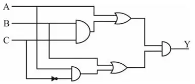
Option C
The given logic circuit contains AND, OR, and NOT gates. We simplify the output step-by-step.
The upper AND gate takes inputs B and C. So, its output is BC. Then this output is ORed with A. Therefore, upper OR gate output becomes A+BC.
In the lower AND gate, the C passes through a NOT gate, producing C’ and A passes directly. So, its output is AC’. Then this output is ORed with B. Therefore, lower OR gate output becomes B+AC’.
The outputs of both OR gates are connected to the final AND gate. Hence, the final output is Y= (A+BC).(B+AC’)
Now, simplify the Boolean expression:
=(A+BC).(B+AC’)
=AB+AAC’+BCB+BCAC’
=AB+AC’+BC+0
=AB+AC’+BC
Now consider the given statement:
I. BC+AC’
II. (A+C)(B+C’)
First consider the statement (II) and simplify:
Statement (II):
=(A+C)(B+C’)
Expanding:
=AB+AC’+BC+CC’
=AB+AC’+BC+0
=AB+AC’+BC
This is exactly equal to the expression obtained from the circuit. Hence, Statement (II) is correct.
Now consider the statement(I), BC+AC’. For this first convert the Boolean expression generated by given circuit in Standard SOP (SSOP) and then solve using K-Map.
Y=AB+AC’+BC
=AB.1+AC’.1+BC.1
=AB(C+C’)+AC’(B+B’)+BC(A+A’)
=ABC+ABC’+ABC’+AB’C’+ABC+A’BC
Now remove redundant term.
=ABC+ABC’+AB’C’+A’BC
Now convert into minterms. As we know in minterms the value of uncomplemented variable is 1 and complemented variable is 0.
| Term | Binary | Decimal |
|---|---|---|
| ABC | 111 | 7 |
| ABC' | 110 | 6 |
| AB'C' | 100 | 4 |
| A'BC | 011 | 3 |
Therefore: Y=∑m(3,4,6,7)
Now plot these minterms into 3-variable K-map and solve.
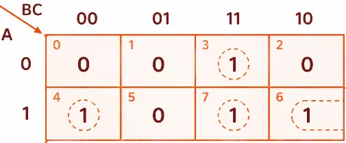
After plotting these minterms on a 3-variable K-Map, two groups are formed. The first pair using minterms 3 and 7 and second pair using minterm 4 and 6.
First Pair = A’BC+ABC= BC
Second Pair = AB’C’+ABC’ = AC’
Thus, Y=BC+AC’
This matches Statement (I).
Therefore, both Statement (I) and Statement (II) are equivalent to the output generated by the circuit.
Q: 13Which one of the following expressions does not represent Exclusive NOR of x and y?
Option D
The Exclusive-NOR (XNOR) function gives output 1 when both inputs are equal. The standard Boolean expression of XNOR is:
x⊙y = xy+x′y′
The option (A) is xy+x′y′. This is the standard form of XNOR.
The option (B) is x⊕y’. Complementing one input of an XOR gate inverts the output, so it becomes XNOR.
In other word, as we know x⊕y is equivalent to x’y+xy’. Similarly, x⊕y’ is equivalent to x’y’+xy’’, which further evaluated to x’y’+xy. This is the standard form of XNOR.
In other words, as we know that x⊕y is equivalent to x′y+xy′. Similarly, x⊕y′ is equivalent to x′y′+xy′′ (replacing y by y’). Since y′′=y, this expression further simplifies to x′y′+xy, which is the standard form of the XNOR function.
The option (C) is x’⊕y. Same logic as option (B).
The option (D) is x’⊕y’. Complementing both inputs of XOR does not change the operation.
The expression x′⊕y′ = x⊕y. This is XOR, not XNOR.
Q: 14The minimum number of NAND gates required to realize AB+AB'C+AB'C' is?
Option D
First simplify the given boolean expression.
=AB+AB’C+AB’C’
=AB+AB’(C+C’)
=AB+AB’.1
=AB+AB’
=A(B+B’)
=A.1
=A
The given expression simplifies to A, so the output can be directly taken from input A. Therefore, the minimum number of NAND gates required is zero.
Q: 15The logical XOR operation of (4AC0)16 and (B53F)16 results?
Option C
The XOR (Exclusive OR) is a logical operation in which the output is 1 when the inputs are different, and the output is 0 when the inputs are the same.
In other words, the output of an XOR gate is 1 when the number of 1’s at the input is odd, otherwise, the output is 0.
XOR operation between (4AC0)16 and (B53F)16:
| Hex Digit (1) | Hex Digit (2) | Binary (1) | Binary (2) | XOR Result | Hex |
|---|---|---|---|---|---|
| 4 | B | 0100 | 1011 | 1111 | F |
| A | 5 | 1010 | 0101 | 1111 | F |
| C | 3 | 1100 | 0011 | 1111 | F |
| 0 | F | 0000 | 1111 | 1111 | F |
So, (4AC0)16 XOR (B53F)16 = (FFFF)16
Thank you so much for taking the time to read my Computer Science MCQs section carefully. Your support and interest mean a lot, and I truly appreciate you being part of this journey. Stay connected for more insights and updates! If you'd like to explore more tutorials and insights, check out my YouTube channel.
Don’t forget to subscribe and stay connected for future updates.
| Student Name | |
|---|---|
| College |
| What's Say |
|---|