
This section contains carefully selected MCQs and Previous Year Questions with explanations to help students understand concepts and prepare effectively for examinations, interviews, and competitive tests.
Q: 1Which of the following represents the borrow in a half subtraction?
Option C
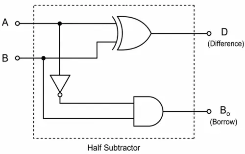
A Half Subtractor is a combinational logic circuit used to subtract one binary bit from another binary bit. It has two inputs and two outputs.
The basic operation is A-B.
Truth Table:
| A | B | Difference (D) | Borrow (B0) |
|---|---|---|---|
| 0 | 0 | 0 | 0 |
| 0 | 1 | 1 | 1 |
| 1 | 0 | 1 | 0 |
| 1 | 1 | 0 | 0 |
From the truth table, the Difference is 1 when the two inputs are different. This is exactly the behavior of an XOR gate.
Therefore, the Boolean expression for Difference is D=A⊕B. The XOR operation can also be written in Boolean algebra as D=A′B+AB′.
The Borrow is 1 only when A=0 and B=1. Therefore, the Boolean expression for Borrow is B0=A′B.
Boolean Expressions:
| Output | Boolean Expression |
|---|---|
| Difference (D) | D=A⊕B = A′B+AB′ |
| Borrow (B0) | B0=A′B |
Circuit Diagram:
Q: 2How many 3 to 8 line decoders are required for a 1 of 32 decoders?
Option C
A 1-of-32 decoder needs 5 input lines because 25 = 32, which means 5 bits can represent 32 different output lines.
A 3-to-8 decoder uses 3 input lines and produces 8 output lines. To design a 1-of-32 decoder using 3-to-8 decoders, the 5 inputs are divided into two groups:
Since 2 input lines can select 22=4 decoders, we need 4 separate 3-to-8 decoders. Each decoder produces 8 outputs, so together they produce, 4*8 = 32 outputs.
Therefore, four 3-to-8 decoders are required to build a 1-of-32 decoder.
Q: 3The number of select inputs required for a 8:1 multiplexer are
Option C
For a multiplexer, the number of select inputs is decided by the relation,
Select Inputs=log2(Number of Data Inputs)
An 8:1 multiplexer has 8 data inputs and only one output, which means we need enough select lines to uniquely choose one of the 8 inputs. Since log2(8) = 3, three select inputs are required.
Q: 4A Decimal to Binary Coded Encoder have ______ inputs and ______ outputs.
Option B
An encoder is a combinational circuit that converts one form of data into another coded form. A Decimal to Binary Coded Encoder converts decimal digits into binary code.
In a decimal number system, there are 10 possible digits from 0 to 9, so a decimal-to-binary encoder requires 10 input lines.
To represent these decimal digits in binary form, 4 output lines are sufficient because 4 binary bits can represent up to 16 different combinations (24 = 16), which easily covers decimal values from 0 to 9.
Q: 5How many select lines are required for an 8 to 1 multiplexer?
Option B
An 8-to-1 multiplexer selects one input out of 8 possible inputs. To uniquely select any one of these 8 inputs, we need enough select lines to represent all combinations. The number of select lines (n) required is determined using the formula 2n=8. Solving this gives n=3.
Q: 6What is the relation between N select inputs and M inputs lines in a multiplexer?
Option B
A Multiplexer (MUX) is a combinational circuit that selects one input from multiple input lines and transfers it to a single output line. The selection of the input line is controlled by select lines.
If a multiplexer has, N select lines, then each select line can have two possible values (0 or 1). Therefore, total possible input combinations become M=2N.
Q: 7In a half-adder circuit, what are the outputs?
Option A
A half-adder is a basic digital circuit used to add two single-bit binary numbers. It produces two outputs:
Q: 8Which of the following is an advantage of use of multiplexers?
I. Logic design is simplified.
II. Minimizes IC package count.
III. Simplification of logic expression is not required.
Option D
A Multiplexer (MUX) is a combinational circuit that selects one of several input lines and sends the selected input to a single output line.
Multiplexers are widely used in digital circuits because they can implement logic functions with relatively few components.
Statement I: Logic design is simplified. (TRUE)
A multiplexer can be used to implement many Boolean functions directly, which can reduce the complexity of the logic circuit.
Statement II: Minimizes IC package count. (TRUE)
Since a single multiplexer can replace several individual logic gates, fewer IC packages may be required to implement a circuit.
Statement III: Simplification of logic expression is not required. (TRUE)
A Boolean function can often be implemented directly using a multiplexer by connecting its inputs appropriately according to the truth table. Therefore, it may not be necessary to simplify the Boolean expression using Boolean algebra or K-map.
Q: 9In a demultiplexer, the number of output lines is n and the number of select lines is m. Which of the following is correct?
Option A
A Demultiplexer (DEMUX) is a combinational circuit that takes one input and directs it to one of several output lines based on the values of the select lines.
If a demultiplexer has m select lines, each select line can have two possible values, 0 or 1. Therefore, m select lines can produce 2m different combinations. Each combination selects one output line. Hence, the number of output lines n is 2m.

Therefore, n=2m.
Q: 10A 2-to-4 line decoder with enable input is to be designed using only NOR gates. The correct minimum number of NOR gates will be
Option C
A Decoder is a combination logic circuit which is similar to demultiplexer but without any data input and used for data decoding.
A 2-to-4 decoder with an enable input has two selection inputs, say A and B, and one enable input E. When the decoder is enabled, exactly one of the four outputs becomes active according to the combination of A and B.
Truth Table:
| ENABLE INPUT | INPUT | OUTPUTS | ||||
|---|---|---|---|---|---|---|
| E | A | B | Y0 | Y1 | Y2 | Y3 |
| 1 | 0 | 0 | 1 | 0 | 0 | 0 |
| 1 | 0 | 1 | 0 | 1 | 0 | 0 |
| 1 | 1 | 0 | 0 | 0 | 1 | 0 |
| 1 | 1 | 1 | 0 | 0 | 0 | 1 |
Boolean Expression:
Y0 = EA’B’
Y1 = EA’B
Y2 = EAB’
Y3 = EAB
To implement these using NOR gates, the required complemented signals are generated first. The four output functions can then be realized using NOR gates. With the standard multi-input NOR-gate implementation, the minimum required number is 7 NOR Gates.
Gate Count:
| Operation | NOR Gates Required |
|---|---|
| Generate A’ | 1 |
| Generate B’ | 1 |
| Generate E’ | 1 |
| Generate Four Decoder Outputs | 4 |
| Total | 7 |
Thank you so much for taking the time to read my Computer Science MCQs section carefully. Your support and interest mean a lot, and I truly appreciate you being part of this journey. Stay connected for more insights and updates! If you'd like to explore more tutorials and insights, check out my YouTube channel.
Don’t forget to subscribe and stay connected for future updates.
| Student Name | |
|---|---|
| College |
| What's Say |
|---|